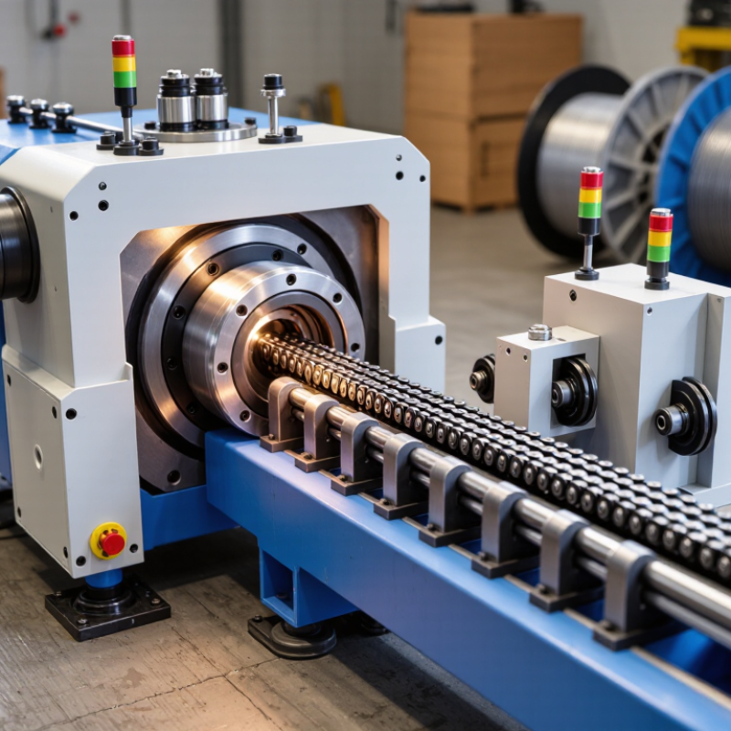
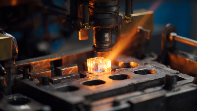
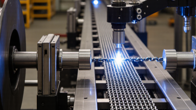
A Cable Chain Coupling Machine is specialized equipment designed to assemble, shape, or connect cable chain coupling components with consistent force and alignment. It supports manufacturing operations where flexible cable systems must transfer motion, absorb vibration, or connect rotating parts safely. The machine may include forming dies, feeding units, tension controls, and inspection sensors.
In practical production, small errors matter. A misaligned link can create noise, uneven movement, or premature wear. The machine helps operators control these risks through repeatable positioning and measured pressure. It can also reduce manual handling during high-volume work. However, performance depends on more than automation. Material quality, chain geometry, tooling condition, and operator judgment remain important.
Mechanical transmission specialist Dr. Elena Marquez explains, “A reliable coupling begins with controlled alignment, not simply faster assembly.” This principle gives the topic a useful engineering foundation. It also reminds readers that machine speed should never replace inspection. That sounds obvious. It is often overlooked.
This guide examines what a Cable Chain Coupling Machine does, how its main systems work, and where manufacturers use it. It will also discuss setup decisions, maintenance points, and common production problems. Some machines appear highly capable but may not suit every cable size or coupling design. A careful evaluation should compare load requirements, tolerances, output targets, and service support. Real factory conditions can be less tidy than technical brochures suggest. Understanding those limits leads to safer choices and more dependable results.
What Is a Cable Chain Coupling Machine?
A cable chain coupling machine joins individual links into a continuous protective chain for moving cables and hoses. In workshops, it may feed links, align pins, press connectors, and verify the finished length. The exact design varies by chain geometry. Some suppliers use “coupling machine” for assembly equipment, while others mean a link-joining station. That distinction matters.
The machine supports cable carriers used on robots, CNC equipment, packaging lines, and automated conveyors. The International Federation of Robotics reported 541,302 industrial robots were installed worldwide in 2023. More moving equipment creates greater demand for reliable cable routing. A coupling machine must control pitch, joint pressure, and alignment. A small offset can cause binding during repeated travel. I have seen operators check this with a slow manual stroke before full-speed testing.
Quality checks should include tensile inspection, bend-cycle testing, and visual review of pin seating. ISO 12100 principles also support risk reduction through guarded pressing zones and controlled access. According to the International Federation of Robotics, automation continues expanding across manufacturing, but cable-chain reliability still depends on basic assembly discipline. The machine is not a magic fix. Lubrication, link tolerance, and cable fill remain important. One assumption can fail. A practical setup records coupling force, chain length, and test results for each production batch.
A cable chain coupling machine is production equipment for assembling interlocking chain sections with coupling parts. The completed assembly guides and protects moving cables. Its design may vary by cable size, chain geometry, and required operating length.
The machine frame supports every working station and keeps alignment stable during assembly. A drive motor moves the chain through controlled forming and joining stages. Feeding rollers deliver plastic or metal links at a steady rate. A guide rail prevents twisting, while a tensioning unit controls slack between sections. This matters because uneven tension can create stiff movement or premature wear.
Forming dies shape each link without crushing its hinge area. Coupling fixtures connect end pieces securely. Some machines use pneumatic cylinders for repeatable pressure. Others use servo actuators for finer position control. Sensors check link presence, length, and missing fasteners. A control panel lets operators adjust speed, stroke, and batch settings. Guarding around moving parts reduces contact risks during operation.
A lubrication point may support smoother hinge movement. Small details matter. Even a clean guide rail can improve consistency. Quality checks should include link spacing, coupling strength, and free movement under light manual force. In practice, setup is rarely perfect on the first attempt. Material variation, tool wear, or incorrect tension may produce subtle defects. Operators should record these findings and adjust the process carefully, rather than trusting appearance alone.
A cable chain coupling machine joins cable chain sections with controlled alignment and pressure. It supports repeatable assembly for industrial cable carriers and flexible protection systems. Operators load chain links, coupling pieces, and fasteners into the machine’s fixtures. Sensors then confirm each component’s position before assembly begins. This matters because a small offset can increase friction during movement.
The process usually starts with feeding chain sections into a guided track. A clamping unit holds both ends firmly. An actuator then presses the coupling piece into the matching connection points. Some machines use pneumatic force, while others use electric servo drives. The controller adjusts speed, pressure, and insertion distance for each cycle. A torque tool may secure screws or locking pins afterward. Inspection sensors check spacing, engagement, and visible damage.
In my experience, the cleanest results come from stable fixtures and carefully adjusted pressure. Excessive force can deform plastic links. Too little force may create a loose joint. That balance is easy to underestimate.
Tips: Keep the guide track free from dust and clipped plastic. Check coupling alignment before increasing production speed. Record failed cycles and inspect their common causes. Manual verification still helps, especially after changing chain sizes. Machine settings should follow measured test results, not assumptions. Also, review sensor calibration regularly because a false reading can pass unnoticed.
What Is a Cable Chain Coupling Machine?
A cable chain coupling machine assembles links, pins, spacers, and side plates into a flexible cable chain. It positions each component, applies controlled pressure, and checks joint movement. This equipment supports consistent pitch and alignment during production. Small errors can cause tight links, uneven travel, or premature wear. In practical workshops, clean feeding paths matter as much as pressing force.
The main type is the pin-coupling machine. It inserts separate pins through prepared link plates. This structure allows easier maintenance and replacement. A rivet-coupling machine forms permanent joints by expanding rivet ends. It usually provides strong retention, but repairs become less convenient. Some machines handle modular snap-fit chains. These use molded sections that lock together without separate metal pins. Their setup is faster, although excessive force may damage the locking shoulders.
Structural differences change the machine’s tooling and inspection method. Pin systems need accurate hole alignment and controlled insertion depth. Rivet systems require stable support beneath the plates. Snap-fit systems need guided pressing surfaces and careful force limits. I have found that a machine can appear accurate while producing uneven joints. That problem often comes from poor material feeding, not the main actuator. Operators should check joint clearance, chain pitch, and side-plate parallelism. Simple gauges help. Visual inspection alone is unreliable. The best configuration depends on chain material, link geometry, production volume, and required flexibility. Even then, the “ideal” setup may need adjustment after real trial runs.
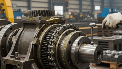
Cable chain coupling machines commonly use two toothed sprockets connected by a roller chain. Single-row designs use one chain row, while double-row designs add a second chain row for greater load distribution. Enclosed versions add a protective, typically split cover around the chain and sprockets. The chart compares representative structural elements rather than manufacturer-specific performance ratings.
What Is a Cable Chain Coupling Machine?
Applications, Selection, and Maintenance Considerations
A cable chain coupling machine assembles or joins carrier-chain sections used to protect cables and hoses. It commonly supports automated equipment, CNC systems, robotic cells, and material-handling lines. The machine controls alignment, joining force, and repeatable spacing. That matters when a chain travels thousands of cycles beside moving machinery. The wrong coupling method can create sharp offsets, noise, or premature cable wear.
Application conditions should guide selection. Check chain width, link geometry, cable weight, travel distance, bending radius, and operating speed. Dust, coolant, heat, and vibration also change the decision. A 2023 report from the International Federation of Robotics recorded 541,302 industrial robot installations worldwide in 2022. This growth increases demand for reliable cable-management systems, especially around moving axes. Yet automation growth alone does not justify buying the fastest machine. Compatibility matters more.
Maintenance is practical, not glamorous. Inspect coupling pins, guides, tooling surfaces, and fasteners during scheduled shutdowns. Remove chips and dried coolant before they harden. Measure unusual play instead of guessing. IEC 60204-1 emphasizes safe electrical equipment practices, but it does not replace mechanical inspection. In my experience, operators often check the cable before checking the chain path. That habit needs reconsideration. A clean assembly can still fail when the bend radius is too small. Keep spare wear parts available, record cycle counts, and review alignment after any collision. Some maintenance plans look complete on paper. They are not always complete in production.
| Category | Data Dimension | Typical Value or Specification | Selection or Maintenance Consideration |
|---|---|---|---|
| Machine Definition and Operating Principle | |||
| Machine function | Primary operation | Automated assembly of cable-chain coupling components | The machine commonly positions links, inserts pins or connecting elements, closes the chain, and performs basic inspection or testing. |
| Coupling structure | Main components | Chain links, pins, side plates, cable-support elements, and end attachments | All component interfaces should be compatible in pitch, hole diameter, material, and assembly tolerance. |
| Motion type | Typical machine motions | Feeding, indexing, clamping, insertion, pressing, and discharge | Servo or pneumatic actuators may be selected according to required positioning accuracy, force, and production rate. |
| Control system | Typical controls | Programmable controller, sensors, safety interlocks, and human-machine interface | Control logic should include part-presence detection, misfeed alarms, emergency stops, and controlled restart procedures. |
| Applications and Production Requirements | |||
| Machine-tool equipment | Typical use | Protection and guided movement of power, signal, hydraulic, or pneumatic lines | Select a coupling assembly process that preserves the chain's articulation and prevents damage to cable-support surfaces. |
| Robotic systems | Typical use | Multi-axis cable routing and repeated flexing applications | Use consistent assembly force and dimensional control because uneven links can increase drag and cable wear during continuous motion. |
| Material-handling systems | Typical use | Transfer equipment, lifting systems, and automated production lines | Consider dust, impact, travel speed, and the frequency of acceleration and deceleration when specifying the machine and coupling. |
| Production volume | Recommended automation level | Manual or semi-automatic for low volume; automatic indexing for repetitive medium or high volume | Automation is most beneficial when part geometry is stable and the same assembly sequence is repeated frequently. |
| Changeover requirement | Typical design feature | Quick-change nests, adjustable guides, and recipe-based settings | For mixed production, prioritize tool-less adjustments, repeatable datum locations, and stored setup parameters. |
| Technical Selection Criteria | |||
| Chain pitch | Dimensional compatibility | Must match the selected chain link and coupling components | Pitch mismatch can cause indexing errors, incomplete engagement, and excessive wear. Verify the supplier's dimensional drawing before tooling. |
| Link width and height | Workpiece envelope | Defined by the selected cable-chain series and its support geometry | Guides, nests, clamps, and discharge chutes must provide sufficient clearance without allowing the link to twist. |
| Assembly force | Pressing or insertion load | Determined by material, interference, pin geometry, and surface finish | Measure the actual assembly load during validation. Excessive force may deform links, while insufficient force can cause loose joints. |
| Positioning accuracy | Typical target | Often specified in the range of ±0.05 to ±0.20 mm for repeatable component placement | The required value depends on the coupling geometry and inspection method. Use a tighter specification only when functionally necessary. |
| Operating speed | Cycle-time planning | Commonly evaluated as parts per minute or seconds per assembly cycle | Confirm that feeder speed, actuator response, inspection time, and downstream handling all support the required takt time. |
| Material compatibility | Common component materials | Engineering plastics, carbon steel, stainless steel, or aluminum | Contact surfaces should resist galling, corrosion, and abrasive wear under the intended environment. |
| Cable-chain configuration | Movement requirements | Horizontal, vertical, lateral, or three-dimensional travel | The assembly process should maintain correct orientation and joint articulation for the final installation direction. |
| Environmental conditions | Operating factors | Temperature, dust, chips, moisture, oil mist, and chemical exposure | Choose sealed sensors, corrosion-resistant tooling, suitable guarding, and compatible lubricants where required. |
| Safety requirements | Essential provisions | Guards, emergency stops, interlocked access, safe pneumatic exhaust, and lockout capability | Risk assessment should address pinch points, stored energy, unexpected actuator movement, and access during clearing of jams. |
| Quality Control and Performance Monitoring | |||
| Visual inspection | Checks | Correct link orientation, complete pin insertion, missing components, and surface damage | Use controlled lighting and defined acceptance samples. Vision sensors can improve repeatability for high-volume production. |
| Dimensional inspection | Checks | Pitch, overall width, joint alignment, and end-attachment position | Inspection frequency should reflect process capability, component variation, and the consequences of assembly failure. |
| Functional test | Checks | Articulation, joint retention, travel smoothness, and abnormal interference | A short movement test can identify stiff joints, incorrect orientation, damaged links, or incomplete engagement. |
| Traceability | Recommended records | Recipe, batch, operator, inspection result, alarm history, and maintenance activity | Traceability supports root-cause analysis and helps distinguish material variation from machine-related defects. |
| Maintenance Considerations | |||
| Daily maintenance | Recommended actions | Remove debris, inspect guides and nests, check sensors, and review alarms | Cleaning should follow the material and contamination requirements. Avoid forcing chips or dust into bearings and actuators. |
| Weekly maintenance | Recommended actions | Check fasteners, feeder alignment, pneumatic tubing, clamps, and visible wear surfaces | Loose hardware or misaligned guides can gradually increase assembly variation and jam frequency. |
| Monthly maintenance | Recommended actions | Verify sensor position, actuator stroke, tooling condition, and safety-device operation | Record measured conditions rather than relying only on visual checks. Replace damaged tooling before it affects product quality. |
| Lubrication | Service interval | Based on component manufacturer instructions, operating hours, load, and contamination | Use only lubricant compatible with bearings, plastics, seals, and the surrounding process. Excess lubricant can attract dust. |
| Wear parts | Common replacement items | Feeder rails, bushings, clamps, seals, insertion tooling, and sensor brackets | Keep critical wear parts available and define replacement limits using dimensional or performance criteria. |
| Troubleshooting: misfeed | Typical causes | Incorrect part orientation, contamination, poor vibration-feed adjustment, or guide wear | Check the feed path first, then confirm part dimensions, sensor signals, and guide clearances. |
| Troubleshooting: incomplete coupling | Typical causes | Insufficient insertion force, incorrect alignment, damaged pin, or incorrect component specification | Stop the machine safely, isolate stored energy, inspect the tooling, and verify the programmed stroke and force settings. |
| Maintenance documentation | Recommended records | Service date, operating hours, replaced parts, measured values, faults, and corrective actions | Trend records can reveal gradual wear before it causes unplanned downtime or a significant increase in rejects. |
| Selection Summary | |||
| Best-fit machine | Decision rule | Match the machine to component geometry, production volume, required quality, and operating environment | Request a process trial using representative components before finalizing the machine, tooling, inspection system, and cycle-time target. |
| Important acceptance criteria | Factory acceptance testing | Stable cycle time, repeatable assembly force, low misfeed rate, complete safety functions, and documented inspection results | Acceptance criteria should be agreed in advance and verified using production-intent materials, tooling, software, and operating conditions. |