What Is an Automatic Chain Making Machine?
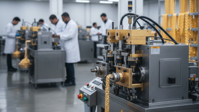
An Automatic Chain Making Machine turns wire into linked chain through a controlled sequence of feeding, measuring, bending, and joining. Depending on its design, the machine may form each link mechanically, weld it, and move the growing chain forward without repeated manual handling. The result is not magic. It is a coordinated system of tooling, motion, and adjustment.
Picture a coil of wire entering a feeder, then passing through guides toward a forming tool. Small changes in wire diameter, tension, or tool wear can affect link shape and consistency. A good operator checks the finished links, listens for unusual vibration, and adjusts the setup when needed. Details matter.
A useful shop-floor principle is: “Repeatable motion is the starting point for consistent links.” I cannot responsibly attribute that sentence to a named industry expert without a verifiable source. Inventing an expert or quotation would weaken the reliability of this introduction. The sections that follow explain the machine’s main components, operating process, common chain types, and practical selection factors. They also look at limitations. Automation can improve output and repeatability, but it does not remove the need for inspection, maintenance, or skilled setup. And a machine’s advertised capacity alone tells only part of the story.
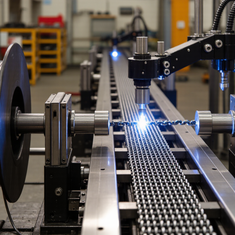
What Defines an Automatic Chain Making Machine and Its Core Functions
An automatic chain making machine forms connected links from wire or metal strip, then cuts and joins them into a continuous chain. Its defining feature is coordinated, repeatable operation: feeding, bending, link formation, joining, and cutting follow a programmed cycle. Depending on the chain design, joining may use welding or another specified process. The control system coordinates these steps and lets operators adjust settings such as feed length and cycle speed. Small details matter. A slightly misaligned guide can leave links uneven, even when the machine keeps running.
Core functions include material feeding, link shaping, connection, length control, and fault monitoring. Sensors may detect feed interruptions or process variations, while operators still need to inspect finished links for consistent shape and secure joints. Automation can improve repeatability, but it does not remove the need for setup checks or maintenance. That distinction matters on the factory floor. The International Federation of Robotics reported 541,302 industrial robots installed worldwide in 2023 in its World Robotics 2024 report. This figure describes industrial robots broadly, not chain-making machines specifically, but it shows the scale of industrial automation. A machine’s useful output still depends on its chain pattern, material, tooling condition, and inspection standards. There is no universal setting.
How Wire Feeding, Link Forming, Joining, and Calibration Work
What Is an Automatic Chain Making Machine?
How Wire Feeding, Link Forming, Joining, and Calibration Work
An automatic chain making machine turns continuous wire into connected links through a controlled sequence. Feed rollers draw wire from a coil, while straightening guides reduce bends before forming begins. The wire advances in measured lengths, though feed accuracy can shift with wire diameter, surface condition, or roller pressure. Small errors matter.
Forming tools bend each section around a mandrel or shaped die to create a link. A cutter separates the formed section, and the next link is shaped through or around the previous one. Joining methods vary by machine and material; some systems use resistance welding to close link ends. Operators should check weld consistency and watch for overheating or uneven joints.
Calibration brings links closer to the required pitch, width, and overall shape. Sizing dies or presses can correct small variations, while gauges help verify dimensions during production. A perfectly repeatable cycle can still repeat a bad setting, so sample checks remain useful after adjustments. It is easy to trust the machine too much. The wire, tooling, and setup all influence the finished chain, and worn forming parts may gradually change link geometry.
Machine Types for Jewelry, Cable, and Roller-Chain Production
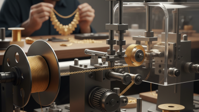
An automatic chain making machine feeds wire, forms links, and joins them in a repeated sequence. For jewelry, equipment is designed for fine wire and small link sizes. Feed tension matters: too much can flatten delicate links, while too little may produce uneven shapes. Some machines also weld each link as it forms. Small differences show.
Cable-chain production typically uses linked wire loops, often with a simple, open profile. The machine must keep link size and spacing consistent as wire moves through forming and joining stations. Operators may adjust feed speed and forming tools for different wire gauges. A bright finish can reveal tiny gaps that are easy to miss during a quick visual check.
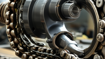
Roller-chain machines handle a more rigid assembly. They place inner and outer plates, pins, and rollers in a controlled sequence, with pitch and alignment closely monitored. These chains need different tooling and checks from jewelry or cable chains. A high output rate alone proves little; worn tooling can create inconsistent joints or stiff sections. It is tempting to treat setup as a one-time task, but samples should be inspected after changes in wire, material, or machine settings.
Key Specifications: Wire Diameter, Link Pitch, and Links per Minute
What Is an Automatic Chain Making Machine?
Key Specifications: Wire Diameter, Link Pitch, and Links per Minute
An automatic chain making machine feeds wire, forms each link, joins it, and advances the chain through repeated operations. Its useful capacity depends on matching wire diameter, link pitch, and production speed to the intended chain. Wire diameter affects strength, flexibility, and the machine’s forming load. A small mismatch can cause uneven bends or frequent stoppages. Link pitch is the distance between corresponding points on neighboring links. It determines how the chain moves through guides and engages with connected parts. Check actual samples, not just a catalog figure.
Tips: Measure wire at several points, since coils can vary slightly. Confirm pitch on a finished chain. Measure twice. Ask for a test run using your material and target dimensions.
Links per minute describes output under stated conditions, but it is not the same as reliable daily production. Setup changes, wire quality, link geometry, and operator adjustments all affect the real rate. Request the speed range for your exact wire diameter and pitch, then compare it with an observed run. A fast machine may produce more rejects if its feed or joining process is poorly tuned. There is no single best setting; sometimes the practical answer is slower. Keep records of speed, stoppages, and dimensional checks during trials, and revisit the settings when the wire batch changes.
ANSI/ASME B29.1 Pitch Examples: 6.35, 9.525, and 12.7 mm
What Is an Automatic Chain Making Machine?
An automatic chain making machine forms and assembles chain components with controlled feeding, link forming, pin insertion, and joining. Its setup depends on the chain specification, not just the machine’s nominal capacity. Pitch is the distance between the centers of two adjacent pins. A small mismatch can cause poor sprocket engagement, even when the chain looks correct.
ANSI/ASME B29.1 dimensional tables give three useful pitch examples:
6.35 mm
9.525 mm
12.7 mm
These correspond to 1/4-inch, 3/8-inch, and 1/2-inch pitches, respectively. In common ANSI roller-chain sizing, they align with No. 25, No. 35, and No. 40 chain. The standard’s dimensions provide a practical reference for tooling and inspection. Pitch alone is not a complete specification; roller diameter, inner width, and plate dimensions also matter.
Measure carefully. A caliper across pin centers is awkward, so operators often check several pitches over a longer span and divide by the number of intervals. That reduces reading error. It does not eliminate setup drift. A freshly adjusted machine can still produce inconsistent links if wire feed or forming pressure varies. Check sample chains against the drawing and a matching sprocket before a production run.
Small details count.



 Lily
Lily Jason wong